International Harvester 1420 Combine - Service Manual


Product Description
This is the complete service manual for the International Harvester 1420 combine.
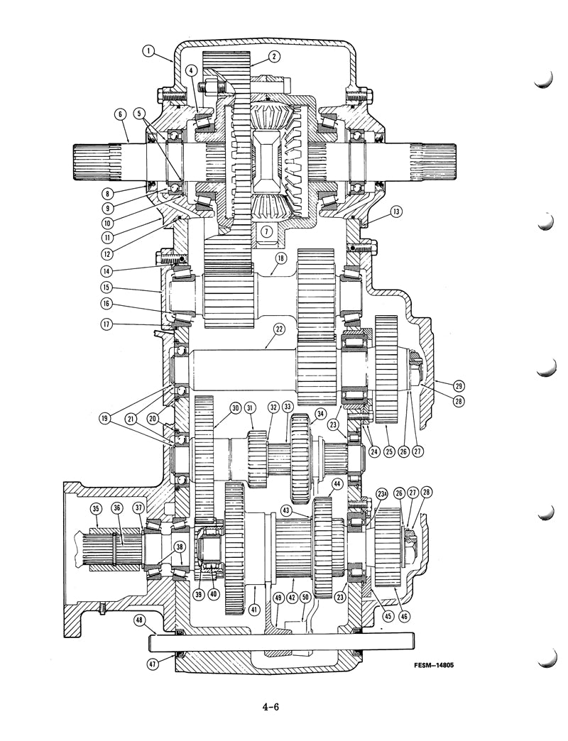
This is the same manual that the dealer repair shops use! It contains hundreds of pictures and diagrams containing all the information you need to repair and troubleshoot your IH harvester.
Covers All Years and Serial Numbers - Other websites sell manuals that are incomplete or only cover a specific year of the machine. This manual is guaranteed to be complete and to cover your machine's model year and serial number.
With over 200 pages this service manual has it all, if you are having trouble with your 1420 combine this manual probably tells you how to fix it.
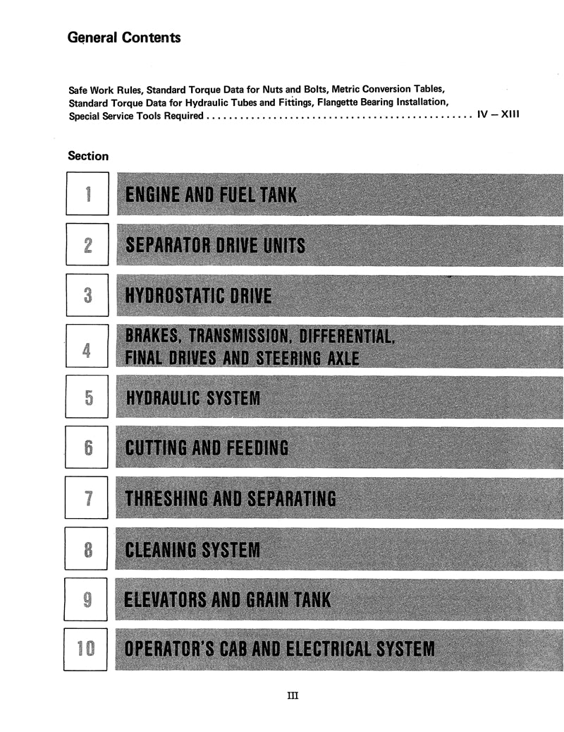
Table of Contents
Manual Details
Payment and Security
Your payment information is processed securely. We do not store credit card details or have access to your credit card information.