Massey Ferguson 550 Combine - COMPLETE Service Manual
Product Description
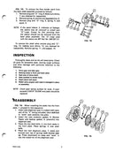
This is the complete 600+ page service manual for the MF 550 combines. Due to the popularity of these service manual in is nearly impossible to find a paper version of the manual.
These service manuals were mostly only used for MF mechanics and its no wonder why. You just have to scroll down to look at the table of contents to see that this service manual has the solution to just about any problem you may be having with your 550 combine.
Covers All Years and Serial Numbers - Other websites sell manuals that are incomplete or only cover a specific year of the machine. This manual is guaranteed to be complete and to cover your machine's model year and serial number.
Table of Contents
Part 1 - General Information
- Safety Precautions
- Recommendations Regarding Service of Combine
- Tightening Torque Chart
- Specifications
- Capacities and Lubrication Data
Part 2 - Engines
- General Information
- Engine Identification/ Serial Number
- General Specifications
- "Running In" Procedure
- General Service Information
- Safety Precautions
- Engine Removal and Installation
- Engine Removal
- Engine Installation
- Engine Overhaul
- GENERAL OVERHAUL INFORMATION
- Tightening Torques
- Engine Overhaul Specifications
- Service "Wear" Limits
- CYLINDER HEAD
- Cylinder Head Removal
- Valve Removal
- Valve Guide Replacement
- Valve and Valve Seat Grinding
- Valve Seat Insert Installation
- Valve Spring Testing
- Valve Installation
- Cylinder Head Resurfacing
- Rocker Shaft Assembly
- Rocker Shaft Disassembly
- Rocker Arm Bushing Replacement
- Rocker Shaft Reassembly
- Cylinder Head Installation
- Cylinder Head Retouring
- Valve Lash Adjustment
- PISTONS AND CONNECTING RODS
- Piston/Connecting Rod Removal
- Piston/Connecting Rod Disassembly
- Piston Inspection
- Piston Servicing
- Connecting Rod Alignment
- Wrist Pin Bushing Replacement
- Piston/Connecting Rod Reassembly
- Piston Rings
- Checking Piston Ring End-Gaps
- Ring Installation on Piston
- Piston/Connecting Rod Installation
- TIMING CASE AND DRIVE
- Front Crankshaft Seal Replacement
- Timing Case Removal (includes backlash and end-play checks)
- Crankshaft Pulley Removal
- Camshaft Gear Removal
- Auxiliary Drive Gear Removal,
- Idler Gears and Hubs
- Camshaft and Tappets
- Camshaft and Tappet Removal
- Camshaft Inspection
- Camshaft and Tappet Installation
- Auxiliary Drive
- Auxiliary Drive Shaft Removal
- Injection Pump Drive Shaft Removal
- Bushing Replacement
- Injection Pump Drive Shaft/Auxiliary Drive Shaft Installation
- Auxiliary Drive Oil Spray Tube
- Timing Case Installation
- CYLINDER BLOCK AND LINERS
- Cylinder Block Inspection
- Cylinder Block Replacement
- Sealing Plug Locations
- Cylinder Liner Servicing
- Cylinder Liner Deglazing
- Cylinder Liner Inspection
- Cylinder Liner Removal
- Cylinder Liner Installation
- FLYWHEEL AND DRIVE PLATE
- Drive Plate, Flywheel, and Flywheel Housing Removal
- Flywheel Ring Gear Replacement
- Flywheel Housing and Flywheel Installation
- Drive Plate Installation
- CRANKSHAFT AND MAIN BEARINGS
- Crankshaft End-Play and Thrust Washer Replacement
- Crankshaft Removal
- Crankshaft Inspection
- Crankshaft Regrinding
- Crankshaft Installation
- Crankshaft Rear Seal Installation
- Lubrication System
- SPECIFICATIONS
- Oil Pump
- Relief Valve
- Oil Filler
- Engine Oil
- DESCRIPTION
- OIL SUMP REMOVAL
- OIL PUMP
- Oil Pump Inspection
- Oil Pump Installation
- OIL RELIEF VALVE
- OIL SUMP INSTALLATION
- Fuel System
- GENERAL INFORMATION
- Description of Operation
- Service Information
- De-rating for Altitude
- SPECIFICATIONS
- Tightening Torques
- Fuel Injection Pump
- Fuel Atomizer Assemblies
- Fuel Lift Pump
- Fuel Filter Assembly
- Fuel Requirements
- AIR BLEEDING THE FUEL SYSTEM
- FUEL INJECTION PUMP
- Injection Pump Removal
- Injection Pump Timing
- Checking Engine Marking Angle
- Checking Injection Pump Marking Angle
- Injection Pump Installation
- Fuel "Shut-Off" Adjustment
- Throttle Control Adjustment
- FUEL ATOMIZER ASSEMBLIES
- Atomizer Removal
- Atomizer Testing —
- Nozzle Opening Pressure Test
- Spray Pattern Test
- Back Leakage Test
- Valve Seat Leakage Test
- Atomizer Parts Sequence
- Atomizer Disassembly
- Inspection
- Cleaning
- Atomizer Reassembly
- Atomizer Installation,
- FUEL LIFT PUMP
- Lift Pump Testing
- Lift Pump Removal,
- Lift Pump Disassembly
- Lift Pump Reassembly
- Lift Pump Installation
- FUEL TANK AND LINES
- Removal/Installation of High Pressure Lines
- Removal/Installation of Low Pressure Lines
- Fuel Strainer Assembly
- FUEL FILTERS
- Changing Fuel Filter Elements,
- Cooling System
- SPECIFICATIONS
- General
- Water Pump
- Thermostats
- Radiator
- COOLING SYSTEM
- Drain Points
- Refilling
- WATER PUMP
- Water Pump Removal
- Water Pump Disassembly
- Water Pump Reassembly
- Water Pump Installation
- THERMOSTATS
- Thermostat Testing
- Thermostat Installation
- RADIATOR
- Radiator Removal
- Radiator Installation
- Engine Trouble-Shooting
- Trouble-Shooting
- Starting Problems
- Running Characteristics
- Checking Cylcinder Compression
- Checking Valve Timing
Part 3 - Power Train
- Engine Output Shaft
- Parts Sequence
- Output Shaft
- Removal
- Servicing
- Installation
- Belt Tension
- Traction Drive
- Drive Belt Removal
- Center Pulley Servicing
- Drive Belt Adjustment
- Checking Belt Tension
- Adjusting Belt Tension
- Variable Speed Traction Drive
- Drive Belt Removal
- Variator Pulley Servicing
- Drive Belt Installation
- Drive Belt Adjustment
- Variator Cyclinder Stop Adjustment
- Low Speed Adjustment
- High Speed Adjustment
- Clutch Assembly (Traction)
- CLUTCH REMOVAL
- Disassembled on Machine (Final Drive Installed)
- Removed as an Assembly (Final Drive Removed)
- CLUTCH DISASSEMBLY
- Clutch Cover Assembly — Servicing
- CLUTCH REASSEMBLY (Includes Release Lever Adjustment)
- CLUTCH INSTALLATION
- Assembled on Machine (Final Drive Installed)
- Installed as an Assembly (Final Drive Removed)
- ADJUSTMENT
- Clutch Pedal Stop Adjustment
- Release Bearing Free-Travel Adjustment
- Transmission - 3-Speed Standard
- Transmission Service Notes
- Differential Service Notes
- Lubrication
- Traction Drive Belt Adjustment
- Transmission Brake Adjustment
- Transmission - Hydrostatic Drive
- Transmission Service Notes
- Differential Service Notes
- Transmission Removal
- Transmission INstallation
- Lubrication
- Transmission - 4 Speed Standard
- Transmission Service Notes
- Differential Service Notes
- Lubrication
- Traction Drive Belt Adjustment
- Transmission Brake
Part 4 - Hydraulics
- Hydraulic Reservoir
- General
- Removal of Return Filter
- Installation of Return Filter
- Removal and Installation of Metallic (Suction) Screen
- Hydraulic Pump
- Operation
- Removal
- Installation
- Disassembly
- Inspection
- Reassembly
- Break-In Procedure (New or Rebuilt Pump)
- Power Steering
- Removal
- Installation
- Disassembly
- Inspection
- Reassembly
- Steering Control Valve
- Removal
- Installation
- Disassembly
- Inspection
- Reassembly
- Steering Cylinder
- Part Number 248 951 M92
- Disassembly
- Inspection
- Reassembly
- Part Number 1748 189 M92
- Disassembly
- Inspection
- Reassembly
- Electro-Hydraulic Header Control Valve (Includes Automatic Header Height Control and Main Control Valve)
- OPERATING DETAILS OF HEADER CONTROL SYSTEM
- OPERATION OF ELECTRO-HYDRAULIC CONTROL VALVE
- DISASSEMBLY AND REASSEMBLY OF THE ELECTRO-HYORAUUC CONTROL VALVE
- AUTOMATIC HEADER HEIGHT CONTROL
- MAIN CONTROL VALVE
- Disassembly and Reassembly
- BENCH TESTING THE ELECTRO-HYDRAUILC CONTROL VALVE
- QUICK TESTS
- TROUBLE-SHOOTING
- Table Lift Cyclinders
- Disassembly and Reassembly
- MF Part NO 264 640 M1
- MF Part NO 3186 329 M92
- Related Hydraulic Cyclinders
- GENERAL
- DISASSEMBLY AND REASSEMBLY
- MF PART NO 261 296 M91 — Reel (Master) Lift Cylinder
- MF PART NO 230 801 M92 — Unloader Swing Cylinder
- MF PART NO 230 774 M94 — Variable Speed Traction Drive Cylinder
- DISASSEMBLY AND REASSEMBLY
- MF PART NO 1748 367 M94 — Reel (Master) Lift Cylinder
- MF PART NO 1748 1 86 M91 — Unloader Swing Cylinder
- MF PART NO 1748 183 M94 — Variable Speed Traction Drive Cylinder
- DISASSEMBLY AND REASSEMBLY
- MF PART NO 1748 122 M94
- Operation of Drive Components
- SAFETY PRECAUTIONS
- RECOMMENDATIONS REGARDING SERVICE OF THE HYDROSTATIC DRIVE SYSTEMS
- OPERATION OF THE EATON HYDROSTATIC DRIVE SYSTEM
- SPECIFICATIONS - EATON
- OPERATION OF THE SUNSTRAND HYDROSTATIC DRIVE SYSTEM
- SPECIFICATIONS — SUNSTRAND
- Hydrostatic Pump - Eaton
- REMOVAL FROM MACHINE
- INSTALLATION IN MACHINE
- INPUT SHAFT HIGH PRESSURE SEAL
- CHARGE PUMP
- CHARGE PRESSURE CHECK VALVES
- CONTROL VALVE
- MAJOR REPAIRS
- START-UP PROCEDURES AFTER SERVICING COMPONENTS
- Hydrostatic Motor - Eaton
- REMOVAL FROM MACHINE
- INSTALLATION ONTO MACHINE
- OUTPUT SHAFT HIGH PRESSURE SEAL
- HIGH PRESSURE RELIEF VALVE (PILOT VALVE)
- SHUTTLE SPOOL
- CHARGE PRESSURE RELIEF VALVES
- MANIFOLD VALVE BLOCK
- MAJOR REPAIRS
- Disassembly
- Reassembly
- Hydrostatic Pump - Sundstrand
- REMOVAL FROM MACHINE
- INSTALLATION IN MACHINE
- INPUT SHAFT HIGH PRESSURE SEAL
- CHARGE PUMP
- CHARGE PRESSURE CHECK VALVES
- CONTROL VALVE
- MAJOR REPAIRS
- START-UP PROCEDURES AFTER SERVICING COMPONENTS
- Hystrostatic Motor - Sundstrand
- REMOVAL FROM MACHINE
- INSTALLATION ONTO MACHINE
- MINOR REPAIRS FIXED DISPLACEMENT MOTOR
- OUTPUT SHAFT HIGH PRESSURE SEAL
- HIGH PRESSURE PILOT VALVE
- SHUTTLE SPOOL
- CHARGE PRESSURE RELIEF VALVE
- MANIFOLD VALVE BLOCK
- MAJOR REPAIRS
- Disassembly
- Reassembly
- Pressure Release Valve
- Operation
- Tests
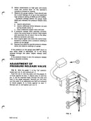
- Adjustment
- Hydraulic System Testing
- General
- Power Steering
- Electro-Hydraulic Header Valve
- Main Control Valve
- Hydraulic System Trouble-Shooting
- Power Steering
- Electro-Hydraulic Header Valve
- Automatic Header Height Control
- Main Control Valve
Part 5 - Electrical System
- Specifications and Wiring Schematics
- SPECIFICATIONS
- Battery
- Maintenance-Free
- Conventional
- Starter Motor
- Alternator
- WIRING SCHEMATICS
- Main Wiring Schematics:
- TC 521, 550 Combines Prior to Serial Number 2121
- TC 522, 550 Combines Serial Number 2121 and Later
- Cab and Air Conditioning Schematic
- Lighting Schematic
- Maintenance-Free Battery
- GENERAL
- VISUAL INSPECTION
- HYDROMETER CHECK
- Green Dot Visible
- Indicator Dark — Green Dot Not Visible
- Indicator Clear or Palo Yellow
- LOAD TEST
- BATTERY CHARGING
- Charging Rates
- Conventional Battery
- ACTIVATING "DRY" BATTERY
- HYDROMETER CHECKS
- Specific Gravity Temperature Conversion
- Hydrometer Cell Comparison
- Electrolyte Freezing Point
- LOAD TEST
- BATTERY CHARGING
- Slow Charging
- Fast Charging
- Charging System
- SCHEMATIC
- ALTERNATOR
- VOLTAGE REGULATOR
- AMMETER
- OIL PRESSURE SWITCH
- MAIN RELAY
- OPERATION
- SYSTEM TESTS
- General
- Battery Voltage and Shorted Isolation Diode Test
- Excitation Voltage Test
- Field Current Test
- Voltage Regulator Operating Voltage Test
- Output Test
- ALTERNATOR
- Removal
- Installation
- Parts Sequence
- Disassembly
- Bearing Removal
- Rectifier Diode Removal
- Component Tests
- Brush Assembly
- Isolation Diode Assembly
- Rectifier Diode Assemblies
- Stator Assembly
- Rotor Assembly
- Reassembly
- Startomg System
- DESCRIPTION
- Starter Motor
- Starter Solenoid
- Safe-Start Switch
- Ignition/Start Switch
- OPERATION
- STARTER SOLENOID
- Testing
- Hold-In Windings Test
- Pull-In Windings Test
- Removal/Installation
- Parts Sequence
- Disassembly/ Reassembly
- STARTER MOTOR
- Testing
- Preliminary Checks
- No Load Test
- Checking Starter Pinion Clearance
- Parts Sequence
- Starter Disassembly
- Shift Lever Removal
- Field Coil Removal
- Field Coil Installation
- Component Testing and Servicing
- Armature Tests
- Armature Servicing
- Field Coil Tests
- Brush Replacement
- Bushing Replacement
- Starter Reassembly
- Starter Lubrication
- Automatic Header Height - Electrical Portion
- DESCRIPTION
- Electro-Hydraulic Control Valve
- Header Switch
- Auto/Manual Switch
- Relay Module
- Reed Switches
- OPERATION
- Manual Mode
- Automatic Mode
- Height of Cut Adjustment
- Electric "Height of Cut" Adjustment
- Manual "Height of Cut" Adjustment
- Sensitivity Adjustment
- SERVICING
- Relay Module
- Reed Switches
- Header Valve Solenoids
- Header Sensing Shaft
- Alarm System
- DESCRIPTION
- SCHEMATIC
- OPERATION
- SENSOR ADJUSTMENT
- Straw Chopper Sensor Adjustment
- Rethresher Sensor Adjustment —
- SYSTEM CIRCUIT TESTS
- Power Supply Test
- Sensor Circuit Test
- Rethresher Sensor Circuit
- Straw Chopper Sensor Circuit
- Sensor Test
- Wiring Harness Test
- Water Temperature Circuit Test
- Speed Switch
- Gauges and Sending Units
- COMPONENTS
- Gauge Cluster
- Engine Oil Pressure Sending Unit
- Engine Coolant Temperature Sending Unit
- Fuel Level Sending Unit
- GAUGE CLUSTER REMOVAL
- GAUGE CLUSTER INSTALLATION
- GAUGE REPLACEMENT
- Trouble-Shooting
- CHARGING SYSTEM
- Alternator Fails to Charge
- Low or Unsteady Charge Rate
- Excessive Charge Rate
- Noisy Alternator
- STARTING SYSTEM
- Nothing Happens
- Solenoid Chatters
- Solenoid Clicks
- Starter Runs Slowly and/or Erratically
- Starter Runs — Won't Engage
- Starter Will Not Release
- AUTOMATIC HEADER HEIGHT CONTROL — ELECTRICAL TROUBLE-SHOOTING
- Header doesn't lower when latched in automatic
- Header lowers but will not raise
Part 6 - Air Conditioning
- Air Conditioning
- SAFETY PRECAUTIONS
- COMPONENTS AND OPERATION OF SYSTEM
- SERVICING THE REFRIGERATION SYSTEM
- Attaching the Gauge Set
- Discharging the System
- Evacuating the System
- Charging the System
- Checking for Leaks
- SERVICING THE SYSTEM COMPONENTS
- Air Conditioning Switch
- Temperature Control Switch
- Blower Switch
- Condenser
- Receiver-Dehydrator
- Thermal Expansion Valve
- Evaporator
- Plenum Chamber
- Compressor
- CAB BLOWER FAN AND MOTOR
- Removal
- Installation
- CHECKING THE COMPRESSOR OIL
- Delco-Frigidaire Air Conditioning Compressor
- SAFETY PRECAUTIONS
- SPECIFICATIONS
- GENERAL
- DISASSEMBLY OF COMPRESSOR
- Hub and Drive Plate
- Pulley and Bearing Assembly
- Shaft Seal Assembly
- Coil Housing Assembly
- ASSEMBLY OF COMPRESSOR
- Coil Housing Assembly
- Pulley and Bearing Assembly
- Shaft Seal Assembly
- Hub and Drive Plate
- Dust Shield
- COMPRESSOR COMPONENTS
- Pressure Relief Valve
- Leak Testing Compressor
- Low Refrigerant Charge Protection
- Thermal Fuse
- Superheat Switch
- Replacement
Part 7 - Wheel and Axle Components
- Final Drive
- Final Drive Service Notes
- Removal
- Installation
- Brake and Brake Systems
- BRAKE DISC SERVICE NOTES
- MASTER CYLINDER
- WHEEL CYLINDER
- ADJUSTMENT
- Master Cylinder Adjustment
- Brake Adjustment
- Parking Brake Adjustment
- Bleeding the Brakes
- Rear Axle
- Steering Axle Assembly
- Wheel Bearings
- Toe-In Adustment
- Equal Travel of Wheels
Part 8 - Header United (Quick-Attach)
- Information
- Knife Drive - MF Part No. 261 445 M91 and 239 731 M96
- Knife Drive - MF Part NO. 261 487 M91
Part 9 - Threashing and Separating Components
- Cyclinder Drive
- TWO-SPEED CYLINDER DRIVE GEARBOX SERVICE NOTES
- CYLINDER DRIVE GEARBOX PULLEY SERVICE NOTES
- CYLINDER DRIVE GEARBOX HOUSING — OUTER
- SHIFT FORK INSTALLATION — UNDRILLED
- GEARBOX ALIGNMENT
- BELT AND PULLEY INSTALLATION
- CYLINDER DRIVE BELT ADJUSTMENT
- LUBRICATION
- Countershaft
- GENERAL INFORMATION
- MAIN DRIVE POLY-'V" PULLEY
- Removal
- Installation
- THRESHING CLUTCH
- Removal
- Service
- Installation
- Adjustment
- CYLINDER DRIVE PULLEY
- Removal
- Installation
- Adjustments
- COUNTERSHAFT REMOVAL
- COUNTERSHAFT SERVICE AND INSTALLATION
Manual Details
Pages: 642 and 3 enlarged pages
Years and Serial Numbers: Covers all years and serial numbers
Models: 550
Make: Massey Ferguson
Manual Code: 1449 200 M1
Manual Type: Service Manual
Payment and Security
Your payment information is processed securely. We do not store credit card details or have access to your credit card information.


