International Harvester 1420 Combine - Service Manual
Product Description
This is the complete service manual for the International Harvester 1420 combine.
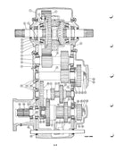
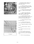
This is the same manual that the dealer repair shops use! It contains hundreds of pictures and diagrams containing all the information you need to repair and troubleshoot your IH harvester.
Covers All Years and Serial Numbers - Other websites sell manuals that are incomplete or only cover a specific year of the machine. This manual is guaranteed to be complete and to cover your machine's model year and serial number.
With over 200 pages this service manual has it all, if you are having trouble with your 1420 combine this manual probably tells you how to fix it.
Table of Contents
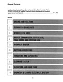
Condensed Table of Contents:
- Engine and Fuel Tank
- Separator Drive Units
- Hydrostatic Drive
- Brakes, Transmission, Differential, Final Drives and Steering Axle
- Hydraulic System
- Cutting and Feeding
- Threshing and Separating
- Cleaning System
- Elevators and Grain Tank
- Operator's Cab and Electrical System
Full Table of Contents:
Engine and Fuel Tank
Specifications
Engine
- Removal
- Installation
Fuel Tank
- Removal
Fuel Tank Sending Unit
- Removal
- Installation
Separator Drive Units
Engine PTO Gear Box
- Removal
- Dissassembly
- Separator Drive Housing
- PTO Bearing Housing
- Reassembly
- Installation
Separator Drive Jackshaft
- Removal
- Disassembly
- Inspection
- Reassembly
- Adjustment
- Installation
Hydrostatic Drive
- Specifications
- Hydrostatic Drive Schematic
- Pump Control Arm Stop Adjustment
- General Information
- Test Procedures
- Hydrostatic Drive Pump
- Hydrostatic Drive Motor
- Foot-N-Inch Valve
- Flushing and Bleeding the Propulsion Drive System
Brakes, Transmission, Differential, Final Drives and Steering Axle
General Description
Specifications
- Special Torques
Ground Travel Speed Chart and Calibration Setting
Transmission Change Gears
- General Information
- Replacing Change Gears
Transmission
- Removal
- Dissassembly
- Motor Adapter and Input Pinion Shaft Assembly
- Shifting Assembly
- Input, Intermediate and Main Shaft Assemblies
- Differential Assembly
- Differential Pinion Shaft Assembly
- Inspection and Repair
- Reassembly
- Differential Pinion Shaft Assembly
- Inspection and Repair
- Reassembly
- Differential Pinion Shaft Assembly
- Differential Assembly
- Intermediate Shaft Assembly
- Main Shaft Assembly
- Input Shaft
- Motor Adapter and Input Pinion Shaft Assembly
- Change Gears
- Shifter Shafts and Forks
- Case Cover
- Installation
Final Drive and Pinion Assembly
- Replacing Final Drive Housing-To-Axle Studs
Brakes
- Description
- Master Brake Cylinder
- Brake Cylinders
- Servicing the Brake Disc
- Bleeding the System
- Brake Adjustment
- Master Cylinder
- Brake Housing
- Parking Brake
Guide Wheel Axle
- Removal
- Installation
Hydraulic System
Hydrostatic Power Steering
- General Description
- Servicing of the Manual Pump
- Steering Cylinder
- Troubleshooting
Electro-Hydraulic Control Valves
- Specifications
- General Description
- How It Works
- Troubleshooting
- Servicing the Stack Valve
- Servicing the Feeder or Separator Clutch Valve (Early Style)
- Servicing the Feeder or Separator Clutch Valve (Later Style)
Automatic Header Control
- General Information
- Controls
- Adjustments
Accumulator
- General Information
- Setting Precharge Pressure With Nitrogen Accumulator Kit
- Setting Precharge Pressure Without Nitrogen Accumulator Kit
Header Lift Cylinders
- General Information
- Servicing the Cylinders
Swing Cylinder
- General Description
- Servicing the Cylinders
Reel Lift Master and Slave Cylinders
- Description and Operation
- Servicing the Master Cylinder
- Servicing the Slave Cylinder
Feeder or Separator Clutch Cylinder
- Servicing the Cylinders
Hydraulic Reel Drive or Windrow Pick-up Drive
- General Information
- Circuit Test
- Servicing the Reel Drive Pump
- Servicing the Reel Drive or Windrow Pick-Up Motor
Hydraulic Pump
- Specifications
- General Description
- Servicing the Pump
Reservoir
Flushing, Cleaning and Purging the Hydraulic System
Cutting and Feeding
- Specifications
- Feeder Gear Housing Assembly
- Removal
- Disassembly
- Inspection
- Reassembly
- Output Shaft
- Input Shaft
- Determine Input Shaft Pinion Mounting Distance
- Check Backlash
- Complete the Assembly
- Installation
Threshing and Separating
Rotor Drive Gear Case and Torque Sensing Unit
- Emoval
- Rotor Drive Torque Sensing Unit
- Rotor Drive Gear Case
- Installation
Rotor
- Removal
- Installation
Rotor Front Bearing Replacement
Auger Bed Assembly
- Augers
- Drive Gears
- Auger and Shaker Drive Shaft
- Auger Bed Bottom
Discharge Beater
- Removal
- Installation
Straw Chopper
- Removal
- Installation
Combine Performance Check
Corn Loss Tables
Seed Loss Tables
Troubleshooting - Threshing and Separator Problems
Cleaning System
Cleaning Fan
- Removal
- Installation
Variable Speed Fan Drive
- Removal
Elevators and Grain Tank
Grain Tank Unloader Vertical Auger
- Removal
Unloader Control Adjustment
Unloader lower Gear Case Assembly
Unloader Upper Gear Case Assembly
Elevator Drive Jackshaft
- Removal
- Installation
Operator's Cab and Electrical System
General Description
Servicing the Components
- Pressurizer Filter
- Pressurizer System
- Heater
- Windshield Wiper Motor
Air Conditioning System
- Specifications
- Evaporator
- Receiver-Dryer Assembly
- Condenser
- Compressor
- Troubleshooting
Shaft Speed Monitoring System
- Troubleshooting
Wire Diagrams
- Air Conditioning
- Audible Alert and Amp. Light
- Electro-Hydraulic Automatic Header Control
- Cigarette Lighter
- Cranking Circuit
- Elevator and Shaker Shaft Warning
- Engine Coolant and Oil Pressure
- Ether Start
- Flaster and Turn Signals
- Fuel System
- Gauge Cluster and Diode Module
- Electro-Hydraulic Header Lift
- Head, Tail and Work Lights
- Ignition and Charging Systems
- Parking Brake
- Electro-Hydraulic Reel Lift
- Electro-Hydraulic Reel Speed
- Separator and Feeder Clutch
- Automatic Feeder Cutoff
- "7"Channel Shaft Speed Monitor
- Electro-Hydraulic Unlaoder Wing
- Variable Rotor Drive
- Warning System
Electrical Specifications
Manual Details
Pages: 340
Years and Serial Numbers: Covers all years and serial numbers
Models: 1420
Make: International Harvester
Manual Code: GSS-1500
Manual Type: Blue Ribbon Service Manual
Payment and Security
Your payment information is processed securely. We do not store credit card details or have access to your credit card information.


