Massey Ferguson 1105, 1135, and 1155 Tractors - Service Manual
Product Description
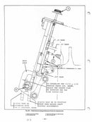
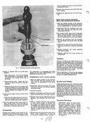
This complete 450+ page service manual covers the Massey Ferguson 1105, 1135, and 1155 tractors. It provides detailed repair, maintenance, and troubleshooting procedures with specifications and diagrams for all major systems.
An essential resource for servicing, repairing, or restoring these Massey Ferguson tractors.
Covers All Years and Serial Numbers - Other websites sell manuals that are incomplete or only cover a specific year of the machine. This manual is guaranteed to be complete and to cover your machine's model year and serial number.
Table of Contents
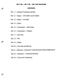
Condensed Table of Contents:
- Important Procedures and Data
- Engine - ATC 6.3541 and AT 6.3541
- Engine — AV 8.540
- Clutch
- Transmission — Multi-Power
- Transmission — 8-Speed
- Drive Axle
- PTO
- Brakes
- Front Axle and Steering
- Hydraulics —Description. Trouble-Shooting, Tests and Adjustments
- Hydraulics — Component Servicing
- Cab and Air Conditioning
Extended Table of Contents
PART ONE – IMPORTANT PROCEDURES AND DATA
- SAFETY PRECAUTIONS
- LUBRICATION AND CAPACITIES
- SERVICE PROCEDURE RECOMMENDATIONS
- ELECTRICAL SYSTEM INFORMATION
- TIGHTENING TORQUE RECOMMENDATIONS
- SPECIAL TOOLS
PART 2 – ATC63541 AND AT63641 DIESEL ENGINES
INTRODUCTION
- ENGINE DATA AND PROCEDURES FOR MF 1105 AND MF 1135 TRACTORS
- General Data
- Engine Component Features
- Engine Removal and Reinstallation Procedures
- Lubrication System Information
- Lubrication System Data
- Removing and Reinstalling Oil Pan
- Fuel and Air System Information
- Fuel and Air System Data
- Air-Bleeding Fuel System
- Replacing Fuel Filter Elements
- Checking and Adjusting Engine Speed
- Checking Turbocharger Boost Pressure
- Cooling System Information
- Cooling System Data
- Adjusting or Replacing Fan Belts
- Removing and Reinstalling Water Pump
- Removing and Reinstalling Radiator
- Engine Electrical System Data
PART 2 – PERKINS DIESEL ENGINES FOR 6372, 63542, T6354, and 6354 DIESEL ENGINES
- ENGINE DESCRIPTION
- TECHNICAL DATA
- PREVENTIVE MAINTENANCE
- FAULT DIAGNOSIS
- CYLINDER HEAD
- PISTONS AND CONNECTING RODS
- CYLINDER BLOCK AND LINERS
- CRANKSHAFT AND MAIN BEARINGS
- TIMING CASE AND DRIVE
- LUBRICATING SYSTEM
- COOLING SYSTEM
- AIR CLEANERS AND FUEL SYSTEM
- FLYWHEEL AND HOUSING
- TURBOCHARGER
- ALTERNATOR AND STARTER MOTOR
PART 2 – HOLSET 3LD TURBOCHARGER
- DESCRIPTION
- TURBOCHARGER LUBRICATION
- IMPORTANT INFORMATION AND PRECAUTIONS
- TROUBLE-SHOOTING
- CHECKING BOOST PRESSURE
- TURBOCHARGER REMOVAL/INSPECTION
- TURBOCHARGER REBUILDING INSTRUCTIONS
- TURBOCHARGER INSTALLATION CHECK LIST
- RUN-IN INSTRUCTIONS FOR A NEW OR REBUILT TURBOCHARGER
PART 2 – AIRESEARCH T-04 TURBOCHARGER
- DESCRIPTION
- OPERATION
- LUBRICATION
- PREVENTATIVE MAINTENANCE
- BEARING CLEARANCE INSPECTION
- Radial Bearing Check
- Axial End-Play Bearing Check
- TROUBLE-SHOOTING
- OVERHAUL INSTRUCTIONS
- Disassembly
- Cleaning
- Inspection
- Reassembly
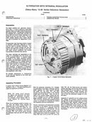
PART 2 – ALTERNATOR WITH INTEGRAL REGULATOR
- DESCRIPTION
- OPERATING PRINCIPLES
- TROUBLE-SHOOTING PROCEDURES
- GENERATOR REPAIR
PART 2 – STARTER MOTOR (Delco-Remy Heavy-Duty Enclosed Shift Lever Type)
- DESCRIPTION
- MAINTENANCE
- ADJUSTABLE HOSE HOUSING
- OPERATION
- TROUBLE-SHOOTING THE CRANKING CIRCUrT
- CRANKING MOTOR TESTS
- DISASSEMBLY
- CLEANING
- ARMATURE SERVICING
- FIELD COIL CHECKS
- FIELD COIL REMOVAL
- CLUTCH ASSEM8LY
- SOLENOID CHECKS
- REASSEMBLY
- LUBRICATION
- PINION CLEARANCE
PART 3 - AVS540 DIESEL ENGINE
- INTRODUCTION
- ENGINE DATA AND PROCEDURES FOR MF 1155 TRACTORS
- General Data
- Lubrication System Data
- Fuel System Data
- Cooling System Data
- Engine Electrical System Data
- Engine Removal and Reinstallation Procedures
- Oil Pan Removal and Reinstallation Procedures
PART 3 – AVS540 DIESEL ENGINE
- Engine Views
- General Information
- Periodical Attentions
- Fault Finding
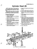
- Cylinder Head
- Pistons and Connecting Rods
- Cylinder Block and Liners
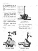
- Crankshaft and Main Bearings
- Timing Case and Drive
- Timing
- Lubricating System
- Cooling System
- Fuel System and Air Filter
- Flywheel and Flywheel Housing
- Auxiliary Drive
- Electrical System
PART 4 – CLUTCH
- DESCRIPTION
- SPLITTING TRACTOR BETWEEN ENGINE AND TRANSMISSION
- RECONNECTING ENGINE TO TRANSMISSION
- REMOVING AND INSTALLING CLUTCH COVER AND DISC
- SERVICING CLUTCH COVER ASSEMBLY
- REPLACING CLUTCH THROWOUT BEARING AND RELEASE FORK
- ADJUSTING CLUTCH PEDAL FREE TRAVEL
- REPACING AND ADJUSTING SAFETY START SWITCH
PART 5 - MULTI-POWER TRANSMISSION
- DESCRIPTION
- SPECIAL TOOLS
- SERVICE INFORMATION
- REMOVING/INSTALLING TRANSMISSION
- DISASSEMBLY OF TRANSMISSION
- INSPECTION AND REASSEMBLY OF TRANSMISSION
- SERVICING MULTI-POWER CLUTCH AND INPUT SHAFT
PART 6 - 8-SPEED TRANSMISSION
- DESCRIPTION
- SPECIAL TOOLS
- SERVICE INFORMATION
- SPLITTING TRACTOR BETWEEN ENGINE AND TRANSMISSION
- CONNECTING ENGINE TO TRANSMISSION
- REMOVING/INSTALLING OPERATOR'S PLATFORM
- REMOVING/INSTALLING INSTRUMENT CONSOLE
- REMOVING/INSTALLING TRANSMISSION
- DISASSEMBLY OF TRANSMISSION
- INSPECTION AND REASSEMBLY OF TRANSMISSION
PART 7 - DRIVE AXLE (with Center Housing, Differential and Pinion)
- SPECIFICATIONS
- General
- Lubrication
- Torque Values
- GENERAL
- Special Tools
- Inspection and Service Notes
- WHEELS AND HUBS
- AXLE HOUSING ASSEMBLY
- Removal
- Installation
- PLANETARY ASSEMBLY
- Removal and Disassembly
- Reassembly and Installation
- AXLE SHAFT SERVICING
- Lubrication
- Servicing
- DIFFERENTIAL ASSEMBLY
- Removal
- Installation
- Differential Lock Servicing
- Disassembly
- Reassembly
- Differential Case Disassembly
- Differential Case Reassembly
- Ring Gear Servicing
- CENTER HOUSING — TRANSMISSION SEPARATION
- HIGH-LOW COUNTERSHAFT
- Removal and Disassembly
- Reassembly and Installation
- DRIVE PINION AND HIGH-LOW RANGE SHIFT
- Removal and Disassembly
- Reassembly and Installation
PART 8 - POWER TAKE
- PTO HOUSING AND REAR SHAFT
- Inspection and Service Notes
- Special Tools
- Removal
- Installation
- Disassembly
- Reassembly
- PTO CLUTCH ASSEMBLY
- Testing — Refer to Part 11 Hydraulic System — Tests and Adjustments
- Removal
- Installation
- Disassembly
- Reassembly
PART 9 - BRAKES
- DESCRIPTION
- BRAKE DISC SERVICING
- BRAKE PISTON SERVICING
- BRAKE MASTER CYLINDER
- BRAKE BLEEDING
PART 10 - FRONT AXLE AND STEERING
- STEERING WHEEL AND SHAFT ASSEMBLY
- Removing/Installing Steering Shaft Assembly
- Servicing Steering Shaft Assembly
- STEERING CONTROL UNIT
- Removing/Installing Steering Control Unit
- Servicing Steering Control Unit
- Replacing Seals Only
- POWER STEERING RACK
- Piston and Cylinder Servicing
- Housing and Power Rack Servicing (Fixed Guide) —
- Housing and Power Rack Servicing (Adjustable Guide)
- FRONT AXLE
- Removing/Installing Front Axle
- Servicing Front Wheel Bearings
- Servicing Front Spindle
- Toe-In Adjustment
PART 11 - HYDRAULIC SYSTEM DESCRIPTION, TROUBLE-SHOOTING, TESTS AND ADJUSTMENTS
- DESCRIPTION
- Low Pressure Circuits
- "Charging" Circuit
- Radial Piston Pump
- High Pressure Circuits
- Brake Circuit
- TROUBLE-SHOOTING CHARTS
- Auxiliary System
- Brake System
- Pressures and Flows
- Steering System
- 3-Point Linkage System
- TESTS AND ADJUSTMENTS
- PRESSURE AND FLOW REFERENCE CHARTS(w/CONDENSED TEST PROCEDURES)
- "Quick-Check"
- "Charging" Circuit
- Low Pressure/Low Volume Circuits
- Radial Piston Pump
- High Pressure Circuits
- Brake Circuit
- "QUICK-CHECK" PROCEDURES
- PREPARING FOR CIRCUIT TESTING
- BRAKE CIRCUIT
- Brake Master Cylinder
- "Bleeding" Brake Circuit
- Adjusting Push Rods (Pedals)
- "CHARGING" CIRCUIT
- Automatic Unloading Valve
- "Charging" Circuit Regulating Valve
- "Charging" Circuit Safety Relief
- "Charging" Pump (Dual Element)
- LOW PRESSURE/LOW VOLUME CIRCUITS
- Differential Lock
- Multi-Power/PTO Valve and Circuits
- PTO Spool Modulation
- HIGH PRESSURE CIRCUITS
- Auxiliary Control Valve
- Adjusting Flow Rate
- Adjusting Lockout Cartridges
- Adjusting Detent on Valve Spool
- Lift Cover and Linkage Control Valve
- Preparing for Tests
- Initial Adjustment of Main Spool
- Position Control (1 st Adjustment)
- Pressure Control (2nd Adjustment)
- Draft Control (3rd Adjustment)
- Response Control (4th Adjustment)
- Control Valve Leakage
- High Pressure Relief Valve
- Priority Valve
- Radial Piston Pump
- Volume Pressure Settings and Adjustments
- Main Relief Valve
- Drain Line Check
- Steering Control Unit and Rack Pistons
PART 12 - HYDRAULIC SYSTEM COMPONENT SERVICING (Removal/ Installation, Disassembly, Inspection, and Reassembly)
- AUXILIARY CONTROL VALVE MF Part Nos 623 782 M91 and 523 783 M91
- BRAKE MASTER CYLINDER MF Part No 528 559 M91
- "CHARGING CIRCUIT" FLOW CONTROL/ PRESSURE REGULATING VALVE MF Part No 520 245 M92
- "CHARGING" PUMP (DUAL ELEMENT) MF Part No 520 257 M92
- DIFFERENTIAL LOCK CONTROL VALVE - MF Part No 528 445 M91
- FRONT COVER ASSEMBLY - MF Part No 528 264 M91
- LIFT COVER ASSEMBLY - MF Part No 530 563 M91
- LIFT CYLINDERS (3-POINT LINKAGE) - MF Pan Nos 514 782 M91 1605 072 M91 and 1605 100 M91
- LINKAGE CONTROL VALVE - MF Part No 521 572 M91
- MULTI-POWER/ PTO CONTROL VALVE
- OIL FILTER (FRONT MOUNTED) - MF Part No 519 206 M93
- OIL INTAKE SCREEN - (RESERVOIR MOUNTED)
- PRIORITY VALVE - MF Pan No 503 977 M93
- RADIAL PISTON PUMP - MF Pan No 530 752 M91
- STEERING CONTROL UNIT
- TRANSFER CAP - MF Pan No 510 013 M91
PART 13 - CAB AND AIR CONDITIONING
- AIR CONDITIONING (Except Compressor Service)
- SAFETY PRECAUTIONS
- DESCRIPTION
- Refrigerant Cycle
- Refrigerant
- Handling Refrigerant
- SPECIAL TOOLS
- SERVICING THE REFRIGERATION SYSTEM
- Performance Test
- False Compressor Seizure
- Checking for Leaks
- Compressor Oil
- Quick Check
- Checking Oil
- Attaching the Gauge Set
- Compressor Port Identification
- Discharging the System
- Evacuating the System
- Charging the System
- Refrigerant-12
- Disconnecting the Gauge Set
- SERVICING SYSTEM COMPONENTS
- Condenser
- Receiver-Dehydrator
- Expansion Valve
- Opening Test
- Closing Test
- Servicing
- Evaporator
- SERVICING THE NON-REFRIGERATION SYSTEM
- Compressor Drive Belt
- Blower Switch
- Temperature Control Switch
- Motor
- Cab Air Intake Filter
- Tractor Engine
- SERVICE DIAGNOSIS
- Refrigerant System
- Electrical Checks
- Trouble-Shooting Charts
- DELCO AIR CONDITIONING COMPRESSOR AND CLUTCH SERVICING USING NUDAY 2390 (ND 105) COMPRESSOR TOOL KIT
- SPECIFICATIONS
- GENERAL
- HUB AND DRIVE PLATE
- PULLEY AND BEARING ASSEMBLY
- COIL HOUSING ASSEMBLY
- SHAFT SEAL ASSEMBLY
- PRESSURE RELIEF VALVE
- LEAK TESTING THE COMPRESSOR
- LOW REFRIGERANT CHARGE PROTECTION
- Thermal Fuse
- TILTING MF 1085, MF 1105, MF 1135 AND MF 1155 TRACTOR CABS USING MFN 730 NUDAY TOOL
Manual Details
Pages: 460
Years and Serial Numbers: Covers all years and serial numbers
Models: 1105, 1135, and 1155
Make: Massey Ferguson
Manual Type: Operator's Manual
Payment and Security
Your payment information is processed securely. We do not store credit card details or have access to your credit card information.


